
Look at any supersonic aircraft and the first similarity you’re likely to notice between all of them is that they’re slim and sleek. Why is that?
It’s all about aerodynamics.
Strictly defined, aerodynamics is the study of fluid that’s in motion and how it interacts with objects that move through it. When an aircraft is said to be aerodynamic, it means it’s shaped in a way to minimize air resistance so the plane can fly faster, farther, and more efficiently.
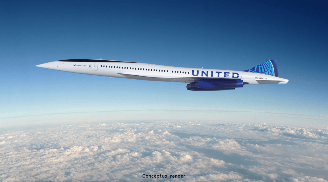
Every aircraft has aerodynamic characteristics. But there are additional considerations that have to be made when flying supersonic. This guide breaks down the major components of supersonic aircraft design and shows our approach to the designs for Overture and XB-1.

4 forces affecting flight: Thrust, drag, weight, and lift
Any aircraft—regardless of whether it’s capable of supersonic speeds or not—has to take into account four forces in order to be able to fly:
➡️ Thrust is the force that moves the plane forward
⬅️ Drag is the opposing force that, pushes the aircraft in the opposite direction of its thrust
⬇️ Weight is the quantification of the result of gravity’s downward force pulling the aircraft’s mass towards the ground
⬆️ Lift is the upward force that can counteract weight
If you’ve ever flown, you’ve experienced all these forces in pretty rapid succession during takeoff. The plane is standing still until sufficient force is applied (thrust), at which point you start moving forward and air pushes back against the plane (drag).
As you accelerate down the runway, you’re still on the ground because the weight of the plane is still too great to be able to fly. It would stay on the ground if not for the shape of the wings, which are generally flat on the bottom and curved on top. The difference in shape results in a higher speed and lower pressure of the air moving across the top of the wing relative to the air below the wing (Bernoulli’s Principle). The overall effect is that this creates zones of high pressure below and low pressure above the wing, which, once you start moving fast enough, lifts the plane off the ground.
As long as thrust remains greater than drag and lift remains greater than weight, the plane will stay in the air. But if you’re planning to go supersonic, there’s an additional wrinkle that you have to take into account.
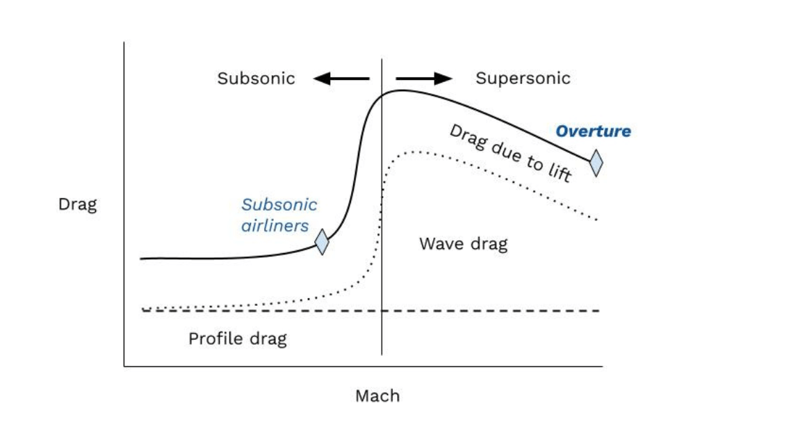
A supersonic challenge: ‘wave drag’
Pressure waves form in front of the aircraft as it accelerates in the air until they coalesce into a strong shock wave. Those shock waves—which are responsible for sonic booms—generate drag as they interact with aircraft surfaces.
This is called “wave drag,” and it can increase drag by 50%, 100%, or more. This requires the engine to produce an equivalent amount of thrust to counter the supersonic drag and keep the plane flying.
Our aerodynamicists have to minimize this effect through tailored design of the aircraft from nose to tail. There are a number of ways engineers tailor aircraft design to meet the supersonic wave drag challenge; here are a few examples.
Swept wings
A “swept wing” design is easiest to understand with a visual comparison. Look at the difference between Overture (left) and a Boeing 777:
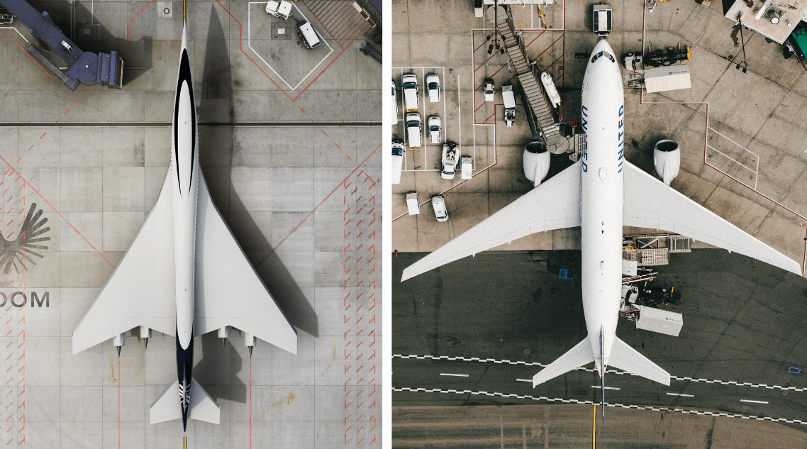
Overture’s wings sweep back at a higher angle than those of the Boeing 777. This maintains local subsonic airflow conditions at the wing’s leading edge as the air interacts with the wing orthogonal to the wing sweep, even at supersonic speeds. This prevents some shock waves from forming and generating additional drag.
Thinner wings
If you changed the perspective of the images above and looked at Overture and the Boeing 777 head-on, you’d also notice that Overture’s wings are thinner. This reduces cross-sectional area and decreases wave drag.
It’s the same conceptual difference between a sports car and a boxy sedan. The sports car will go faster because it has a stronger engine, of course. But it will also encounter less air resistance because it’s thinner and more streamlined.
Contoured fuselage
One other unique feature of Overture is that its fuselage gets narrower from front to back. If you imagine the shape of a typical airliner’s fuselage as the cardboard tube in the center of a roll of paper towels, Overture’s is more Coke-bottle-shaped (wider in front, thinner in back).
Doing this smoothes the aircraft’s volume distribution from nose to tail and reduces wave drag. The fuselage wants to be larger in the areas away from the wing and engine nacelles to blend the volume progression.
Like I mentioned above, these are just a few examples. There are many other considerations that go into designing a supersonic aircraft. One that factored heavily into Overture’s production design was the need for it to fly efficiently at supersonic and subsonic speeds.
Designing for the ‘distance’ between sub- and supersonic
Design features that work best at supersonic speeds don’t always work best at subsonic speeds, and vice versa. This divide is a design challenge.
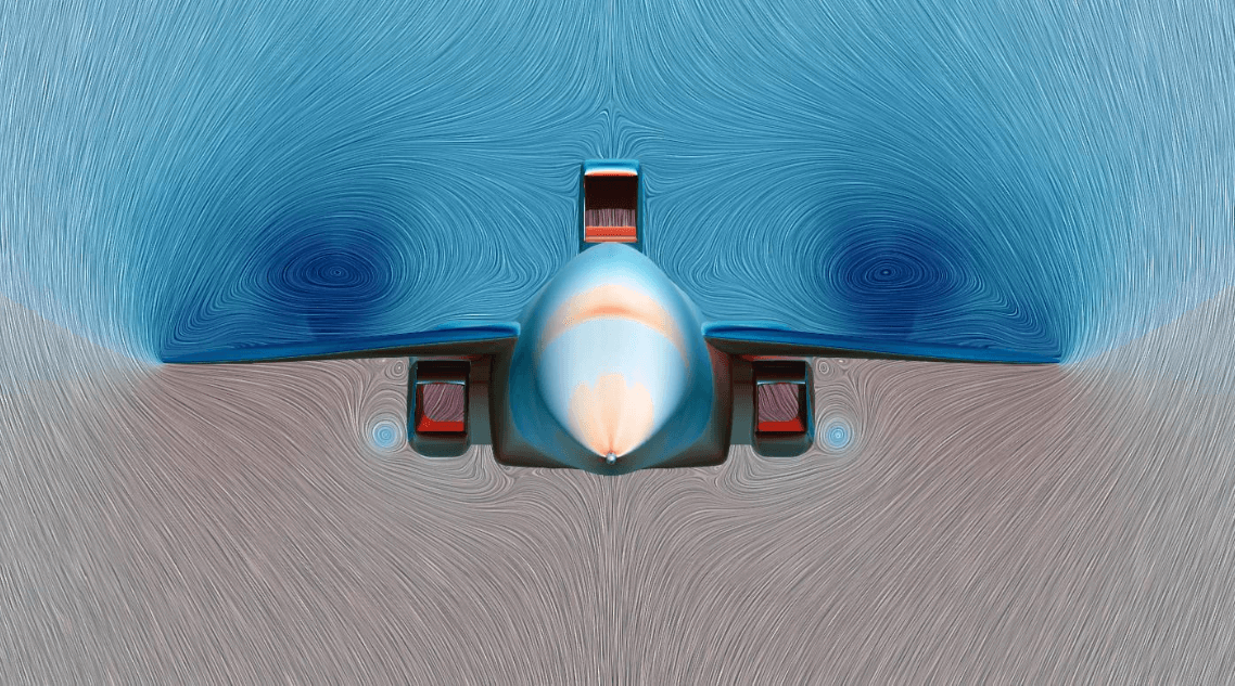
Consider the swept wing referenced above—this isn’t an ideal wing design for typical takeoff and landing speeds. So, to augment performance at low speeds, a series of flap surfaces exist on the wing to fundamentally change its aerodynamic properties and accommodate slower speeds at takeoff and landing.
The swept wing is much less susceptible to stalls compared to common subsonic airliners because of vortices (swirling sections of air; see image below) that are generated at the leading edge of the wing and boost lift. This extra boost, however, increases drag once again, which must be assessed in the design process to ensure adequate performance when Overture is flying near an airfield.
We also need to consider our community impact. As we improve our aerodynamics at low speeds, we generate less noise from the airframe (as it moves through and impacts the air) and the engines, as they adjust to overpower drag. The upshot is that Overture will sound just as quiet as a typical airliner when it takes off from your local airport.
Design trades
There are many competing variables that engineers must balance to meet an aircraft’s design objectives. We call these trades.
Most design trades must map back to an equation used to calculate an aircraft’s range (how far it can fly) called the Breguet Range Equation. This equation details how the aircraft’s aerodynamic efficiency, propulsion efficiency, and non-fuel weight (structural, packaging, and payload efficiency) determine the range the aircraft can fly.
Range is one of the main design objectives for any transport aircraft. If cruise speed is increased in the Breguet Range Equation, if all other properties are equal, range would go up as well. But remember, supersonic speeds create wave drag that will reduce the aerodynamic lift-to-drag ratio (L/D) as drag increases. This is what is meant by aerodynamic efficiency. Aerodynamicists are charged with designing a wing and configuration that has as high a L/D as feasible, consistent with the aircraft’s design speed, to maximize the range of the vehicle.
Let’s dig a little deeper. There are two other key components to the range equation:
- Specific fuel consumption (SFC) is determined by the engine and its installation of an efficient inlet and exhaust nozzle. A more efficient engine decreases SFC, which in turn increases the range. In everyday terms for drivers, when your car’s engine is more efficient, you can drive farther with the same amount of gas.
- Non-Fuel Weight is determined by how much the aircraft is carrying as payload (passengers, luggage, operating equipment), the need for systems to support the safe operation of the aircraft, and the efficiency of the aircraft’s structural design. The greater the share of payload that’s taken up by fuel itself, the greater the range of the aircraft.
This only begins to describe the “grand compromise” that is aircraft design.
For example, an aerodynamicist might want wings that are as thin as possible to decrease supersonic drag and increase lift-to-drag radio and range. But a thinner wing also means a heavier wing relative to the fuel it can hold, which decreases range. A middle ground—or trade—must be found as the compromise for both.
A note on materials
At any single point in the sky, the type of materials we use (e.g. aluminum vs. carbon composite) have an effect on aerodynamic performance. The materials and structure define how the vehicle changes shape at different speeds and altitudes. These small shape changes alter the aerodynamic properties of the vehicle and thus its performance.
This is accounted for in the design process through iteration of materials, structural layout, and aerodynamic performance. The first thing we do is define the shape of the vehicle in the most critical area where it will fly: supersonic cruise altitude and speed. Then, we solve for other operating contexts (subsonic flight, taxiing, etc.) and assess them for acceptable performance.
Testing: Where it all comes together
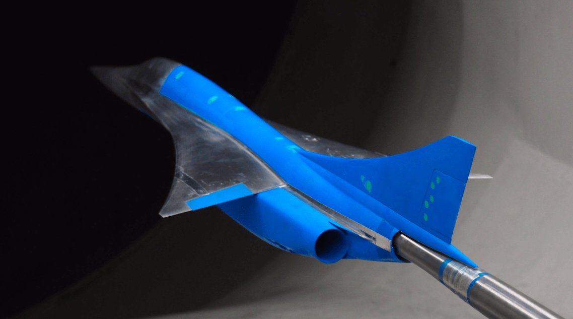
Balancing all these concepts and turning them into a working airplane design is no small task. The production design of Overture was the result of 26 million core-hours of simulated software designs, five wind tunnel tests, and 51 full design iterations.
Early design stages use fast computational methods to understand broad trends in aircraft design. As the process matures, increasingly expensive computational methods are used to predict the performance of a design. Only a few of the most promising designs can be used in the highest fidelity computational fluid dynamics (CFD) runs or wind tunnel testing.
Both computational methods and experimental (real-life) methods have their flaws. Boom used the combination of them together to design both XB-1 and Overture.
Wind tunnel testing can have different goals. These could include calibrating computational prediction methods, exploring different design trades like tail size or aileron span, obtaining control power increments to ultimately be used in a flight simulator, and obtaining critical performance data like lift and drag.
We work with model makers to manufacture a scaled model of a design and then take that model to a wind tunnel facility to test. Different wind tunnel facilities specialize in different things. They can:
- specialize in low speed airflow;
- provide a wide range of airflow speeds;
- and simulate different altitudes of flights by varying pressure and density in a tunnel.
The last step is to compare our wind tunnel tests to computational results. This allows us to augment simulated physics with experimentally measured physics to increase the accuracy of the aircraft models predictions
If you’d like to know more about our aircraft, visit our pages dedicated to Overture and XB-1.